ENGINEERING SCOPE
Technology With Clear Boundaries.
Understand the architecture, integration points and operating checks behind IFUNGOO electric propulsion systems–without extending a model-specific specification into a product-wide promise.
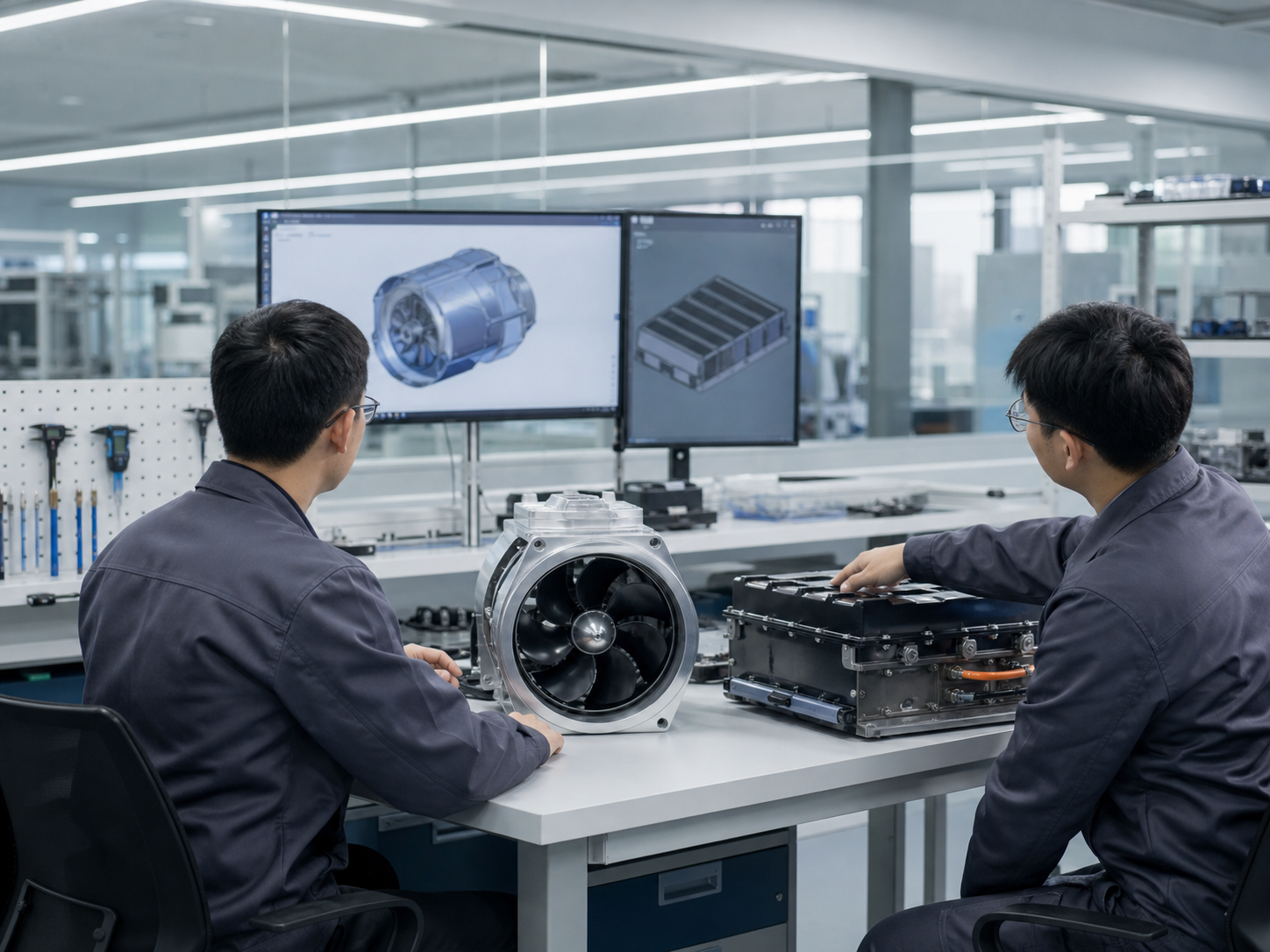
EVIDENCE PRINCIPLE
A specification, certificate or compatibility statement applies only to the named model, configuration and documented scope.
01
Architecture
Motor, drive, vessel and battery as an integrated selection problem.
02
Protection
Electrical, battery and installation safeguards require correct use.
03
Support
Move from evaluation to documentation, integration and scale-up.
MOTOR & DRIVE ARCHITECTURE
Start With the Complete Propulsion Path.
A motor does not operate in isolation. Selection should connect the thruster, battery voltage, steering or mounting arrangement, vessel and intended duty cycle.
SYSTEM LOGIC
CONCEPTUAL DIAGRAM
Battery
Voltage & capacity
Drive path
Configuration-specific
Thruster
Model-specific output
Vessel
Load & water conditions
Architecture decisions must be checked against the selected model and installation. The diagram is a selection framework, not a universal wiring diagram.
Compact to higher power
Supplied materials list Y04 at 330W and approximately 8 kgf, Y01 at 600W and approximately 13.5 kgf, and H01 at 2000W and approximately 35 kgf.
Evidence scope: named model specifications. These figures are not a product-wide performance claim.
Y02D servo-steering thruster
The current product record lists 500W rated power and 11.5 kgf maximum thrust. Use the model page and compatibility review for configuration-specific decisions.
HYDRODYNAMIC CONSIDERATIONS
Thrust Is Only One Part of the Result.
Real-world speed, range and runtime depend on the vessel shape, total load, installation, battery state, current and weather. Compare results only when test conditions are documented.
CHECK THE CONTEXT
- Craft type, hull or board geometry
- Total occupants, equipment and battery load
- Mount position, immersion and alignment
- Water conditions and operating duty cycle
SIMPLIFIED FLOW DIAGRAM
Conceptual illustration only. It does not define installation dimensions or guarantee speed.
PROTECTION & OPERATING SCOPE
Protection Is a System Responsibility.
Electrical protection, waterproofing, battery care and installation quality must be reviewed for the selected product and use case. No single model-specific rating should be extended across the full catalog.
Electrical protection
Confirm voltage, connection arrangement, cable routing and installation instructions for the selected motor, battery and mount combination before energizing the system.
Scope: integration guidance. A complete protection specification must be confirmed from the applicable product documentation.
Waterproofing scope
Water resistance or an IP rating, where documented, belongs to the named product and test scope. Correct installation, connector inspection, freshwater rinsing after saltwater use, drying and storage remain necessary.
Do not treat one model’s rating as a range-wide or installation-wide approval.
Battery protection
Match battery voltage and capacity to the intended propulsion configuration. Protect batteries from impact, unsuitable storage conditions, moisture exposure and unconfirmed charging arrangements.
Battery chemistry and certification scope must be confirmed by the applicable battery documentation.
Installation integration
Verify mount strength, alignment, immersion, steering movement, cable clearance and emergency access on the actual craft before local testing or commercial deployment.
Final installation responsibility depends on the vessel, integrator and applicable local requirements.
COMPATIBILITY DISCLOSURE
Compatibility Belongs to the Named Configuration.
Use the following confirmed examples as starting points for evaluation. They do not replace a model, vessel or installation review.
| Named item | Documented relationship | Scope note |
|---|---|---|
| H01 Electric Thruster | Compatible with B30H and B50H | Named compatibility only; confirm vessel and installation conditions. |
| 1500W Inverter | Compatible only with B30H and B50H | Do not extend this relationship to other batteries. |
| SEAKOOL Fisherman Inflatable Paddle Board | Supplied materials state compatibility with current IFUNGOO electric thrusters | Confirm load, mounting arrangement and operating conditions for each project. |
| Y03 Dual-Drive Evaluation System | Two Y03 thrusters and two B3 batteries | Evaluation configuration for compatibility and local testing, not a universal package. |
PRE-OPERATION CHECKS
Check the Installation Before the Water.
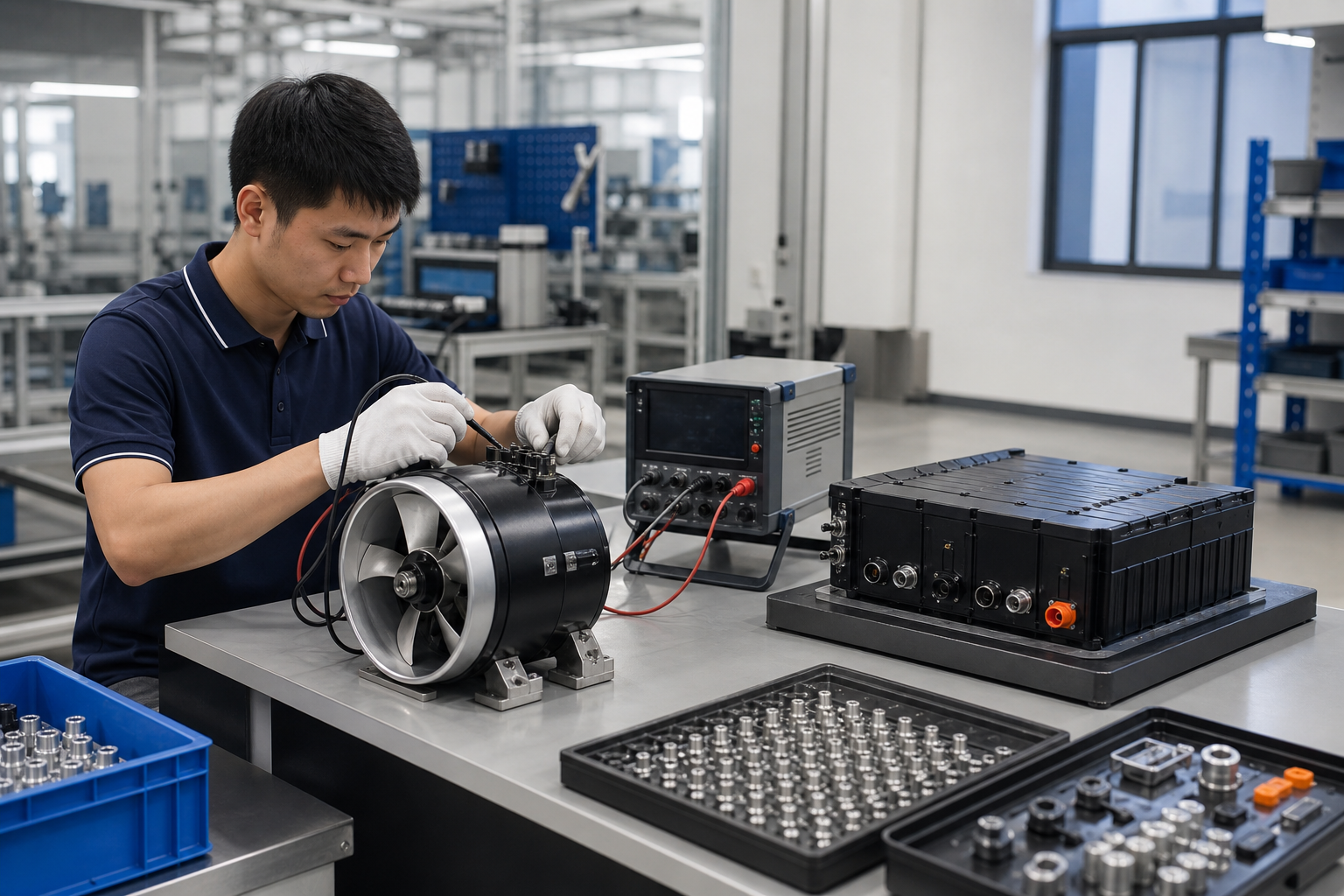
A concise inspection sequence helps teams identify integration issues before evaluation or commercial use. Use the product manual and local requirements for the final procedure.
STOP CONDITION
Do not operate when a connection, mount, cable, battery or steering movement is damaged, loose or outside the documented configuration.
-
01
Confirm the model
Check that the motor, battery, mount and accessory match the approved project configuration.
-
02
Inspect connections
Check connectors, cables, routing, insulation and signs of moisture, corrosion or impact.
-
03
Verify the mount
Confirm secure attachment, alignment, immersion, clearance and full steering movement.
-
04
Review the environment
Account for vessel load, weather, current, operating area and the intended test plan.
MAINTENANCE & UPGRADE SUPPORT
From First Evaluation to Next Revision.
Support should follow the project stage: inspect the current installation, document the operating issue, confirm replacement or upgrade scope, then retest the complete configuration.
01
Diagnose
Record model, symptoms, environment, connections and recent changes.
02
Confirm
Review documents, compatibility, replacement scope and installation constraints.
03
Retest
Validate the revised system under recorded vessel and operating conditions.
EVIDENCE-FIRST WORKFLOW
Build the Decision From the Record.
Product records, document scope, compatibility notes and test conditions should travel with the project from sample evaluation to commercial planning.
PRODUCT RECORD
Named model
Use the model’s stated specifications, verification status and known conflicts.
DOCUMENT RECORD
Defined scope
Identify the applicable product, issuer, status, version and issue date before relying on a document.
TEST RECORD
Recorded conditions
Capture craft, load, battery configuration, installation, water and weather conditions.
Need a model-specific compatibility review, evaluation configuration or OEM integration discussion?